Elipse Power automates Energisa’s Padre Fialho substation in Brazil
Application developed by Energia Automação allows controlling all devices at the substation located in Matipó (MG), in the Brazilian Southeast

Needs
The Energisa Group is one of the main private players in the Brazilian electric sector, providing this market with distribution, generation, and commercialization solutions. Energy distribution is the company’s core business: With five utilities in Brazil (three in the country’s Northeast–Energisa Sergipe, Energisa Paraíba, and Energisa Borborema–, one in the Southeast’s mesoregion called Zona da Mata–Energisa Minas Gerais–, and one in Rio de Janeiro’s mountain city of Nova Friburgo–Energisa Nova Friburgo), Energisa covers 91.18 Km² of Brazilian territory. This means 2.4 million consumers, in an area with 352 municipalities and 6.7 million inhabitants. Currently, the company employs a workforce of over 5,500 people, between direct and indirect collaborators.
In order to modernize its Padre Fialho substation, in Matipó (MG), Energisa Solutions decided to adopt Elipse Power, the smart management solution for electrical systems developed by Elipse Software. The substation’s protection relays and electronic panels were supplied by SEL – Schweitzer Engineering Laboratories; and the HMI application was developed by Energia Automação. With it, operators can monitor and control the different devices in the substation both remotely and in real time.
Solution
Since November 2011, Elipse Power has run locally in the substation, in a SEL dedicated computer, model SEL-3354, with two monitors that can be operated directly via 15-inch touch screens, working as a human-machine interface (HMI). The application exchanges information with the substation devices, communicating directly with several SEL protection relays via IEC61850 protocol and TCP/IP network.
For a safer operation, the supervisory system’s architecture is Hot-Standby, that is, there is another computer, also SEL-3354, working as a standby server to take over communication and data process whenever the main computer fails. Additionally, the application sends data from Energisa’s System Operations Center (SOC) to the supervisory via DNP3.0 protocol.
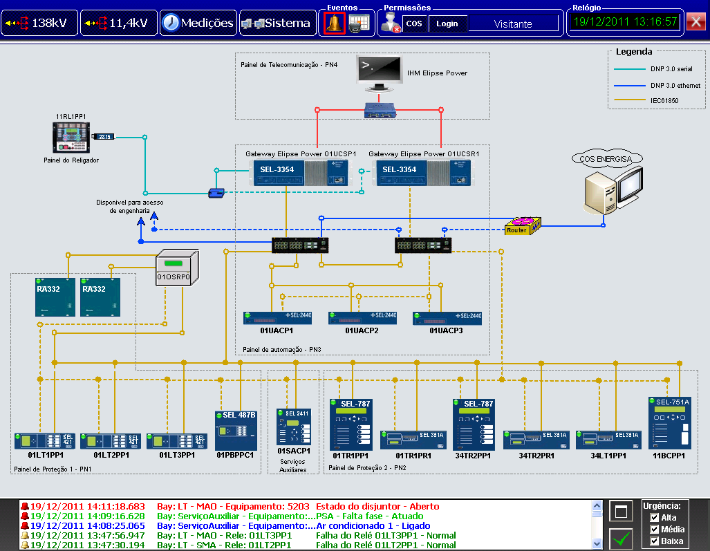
Figure 1. System’s architecture
That way, Elipse Power works as a gateway between IEC61850 and DNP3.0 protocols, which in turn enables integrating the remote center users to the substation’s field equipment. Therefore, the SOC users get real-time information about any actions taken regarding protection, discrete alterations, and the equipment’s measurement values.
In addition to access to all this data, whenever the commands control is directed to the SOC, operators can handle maneuvers via commands to the substation’s HMI. Through a series of screens, users have access to the field devices’ information, which are reported to protection relays, to the automation system’s architecture, and to the substations’ alarms/events.
138kV and 11.4kV screens
The system displays two screens where users can access the substation’s high (138kV) and low (11.4kV) voltage sides, thus retrieving information about the electrical connectivity between devices, the status of discrete measurements, protection actions, analog measurements, and the system’s bays energized/deenergized status.
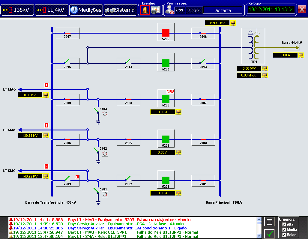
Figure 2. Screen displaying the high voltage side
Popup screens
In order to supply each device in the substation with a detailed interface, the application uses popup screens, which allow users to send commands, check analog and discrete information, and visualize alarms/events. That way, users can visualize all the details regarding a single breaker in the substation, for example; they can also send open/close commands, activate or block its reclose, as well as monitor electric currents and active/reactive outputs, among other variables relating to this device.
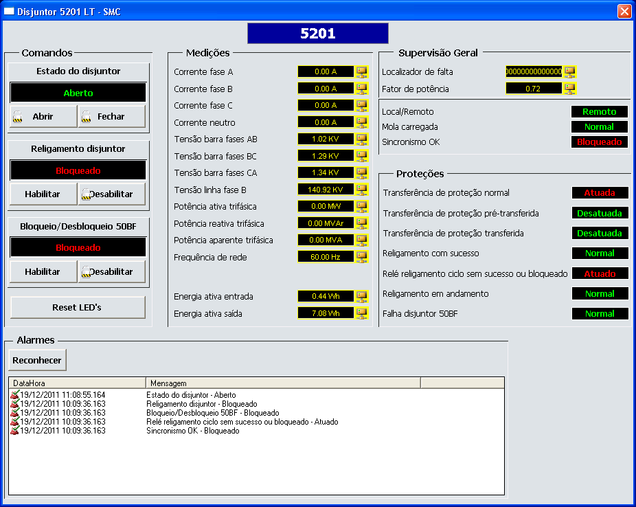
Figure 3. Screen displaying all data regarding 5201 breaker
Alarms summary
With the online alarms summary, users are constantly kept updated on the occurrences verified in the substation in real time. Therefore, any alteration in the system indicating some sort of abnormality is highlighted on a row with its respective date/time, bay, device, and a message describing the issue.
Additionally, the alarm severity system is color coded; that is, a high-severity alarm is displayed in light red, a medium severity alarm is displayed in light green, and a low-severity alarm is displayed in light blue.
Acknowledged alarms are color coded as follows: high severity is dark red, medium severity is dark green, and low severity is dark blue. Inactive alarms, events, or commands are displayed in black.
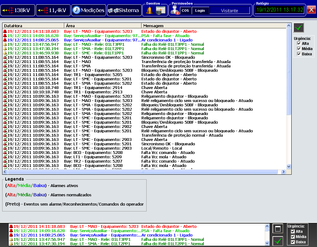
Figure 4. Alarms summary
Alarms history
Users can browse any alarms, events, and user-generated commands from the application’s history via a screen that displays the information stored in the database. On this screen, users can retrieve the timestamp of when the alarm goes on/out or is acknowledged, which makes it easier to detect the reasons why the relays have activated any protection measures, for example.
Information can be filtered by timestamp, status (active, inactive, or acknowledged), type (alarm, event, or command), and severity (high, medium, or low). The same color code used for the alarms summary applies to the history (red = high severity; green = medium; and blue = low). Additionally, the document can also be exported as a .CSV report.
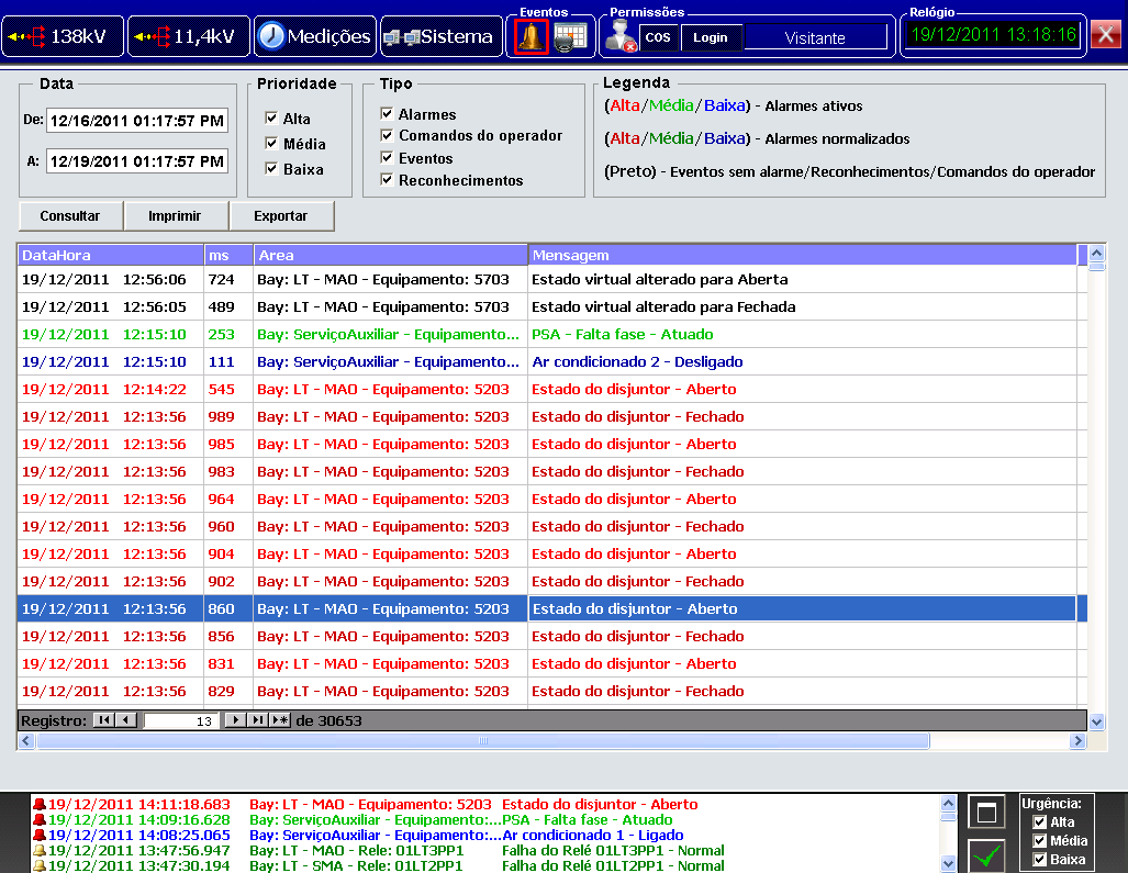
Figure 5. Alarms history
Measurements
There are three different screens where users can follow different variables for current, output, voltage, and frequency, in addition to being able to check the precise spot where the transmission network has failed. These values are measured next to each device inside the substation bay. To do so, screens provide the measurements online via a group of displays that are updated in real time.
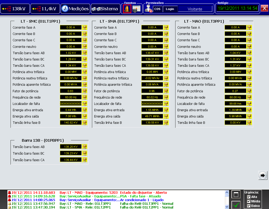
Figure 6. Screen displaying a few measurements signaled with the substation
Benefits
- Access control to Elipse Power via login and password.
- Quick, comprehensive view of all the devices composing the substation’s automation and protection system’s architecture.
- Detailed information on the online and historic occurrences.
- Remote control of all devices in the substation (such as switches, breakers, sectionalizers, and transformers, among others).
- Substation’s single-line diagram monitored in real time.
- Interface between SOC systems and the substation’s devices.
Datasheet
Client: Energisa Soluções
Systems Integrator: Energia Automação
Elipse product: Elipse Power
Number of copies: 1 (Elipse Power 5000 Hot-Standby + 2 Viewers)
Platform: Windows XP
Number of I/O points: 2,000
I/O driver: IEC61850 and DNP3.0
