Elipse E3 optimizes the control of CPFL Power Group’s 17 SHPC
This case presents the Elipse E3 application devised to control the different steps related to power generation performed by a total of CPFL Power Group's 17 Small Hydro Power Centrals (SHPC)
Needs
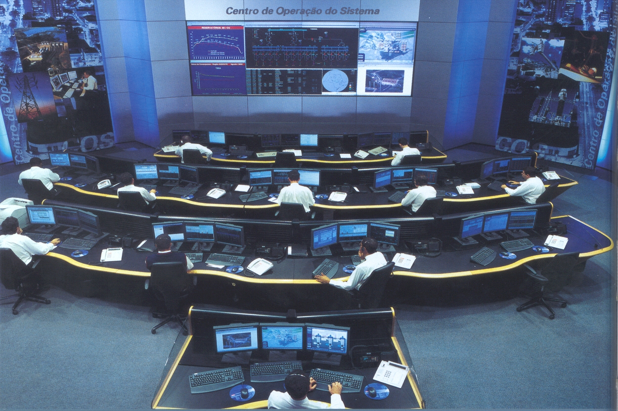
Figure 1. Generation Operations Center
CPFL Power Group is a holding company operating in the Brazilian electricity sector for almost a century. Its subsidiaries are dedicated to power distribution, generation, and trading. CPFL is considered the largest private company in the Brazilian power sector, with 19 SHPCs and a thermal power plant, with total installed capacity of 120 MW and 36 MW respectively, all of them located in the State of São Paulo. For this purpose, the dealership has a wide network of partners, and is always looking for talented partners in Brazil and abroad to invest their resources in an efficient and qualified way.
One of these partners is Elipse Software, a company specialized in developing solutions for process management. One such solution is Elipse E3, the software adopted by CPFL to assist operators in the Generation Operation Center (GOC) to control a total of 17 Small Hydro Power Centrals (SHPCs). They are: Americana, Buritis, Pinhal, Chibarro, Capão Preto, Dourados, Eloy Chaves, Esmeril, Jaguari, São Joaquim, Lençóis, Monjolinho, Santana, Salto Grande, Socorro, Três Saltos, and Gavião Peixoto. The system consists of 16 Elipse E3 copies, and each of the 17 stations were supplied its own E3 Server.
Solution
Elipse E3 enables operators from the Generation Operation Center to monitor all parts and devices comprising the 17 SHPCs. Thus, the software optimizes control reports, in real time, via their screens, all details of any occurrence that may reach one of the plants.
To access the system, first a password is required on the home screen of the supervisory, which illustrates the 17 SHPCs distributed on the map of the State of São Paulo. Once entry into the system is authorized, the operator can choose which stage of power generation or device needs to be monitored.
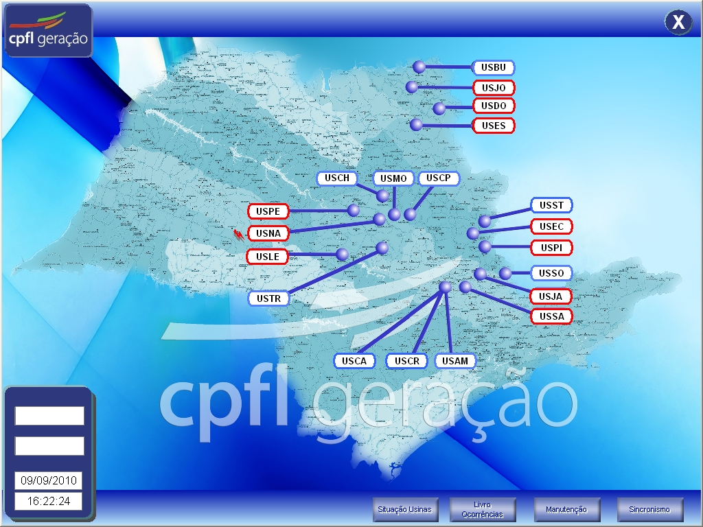
Figure 2. Initial application screen
Water intake
Once access is released, the software provides the user with other screens. The first one allows them to monitor the “water intake” stage, which is characterized by the impound of river water that is initially driven to the cargo chambers’ interior, and then to the turbines. The water intake is located near or on the weir (dam) of the SHPC.
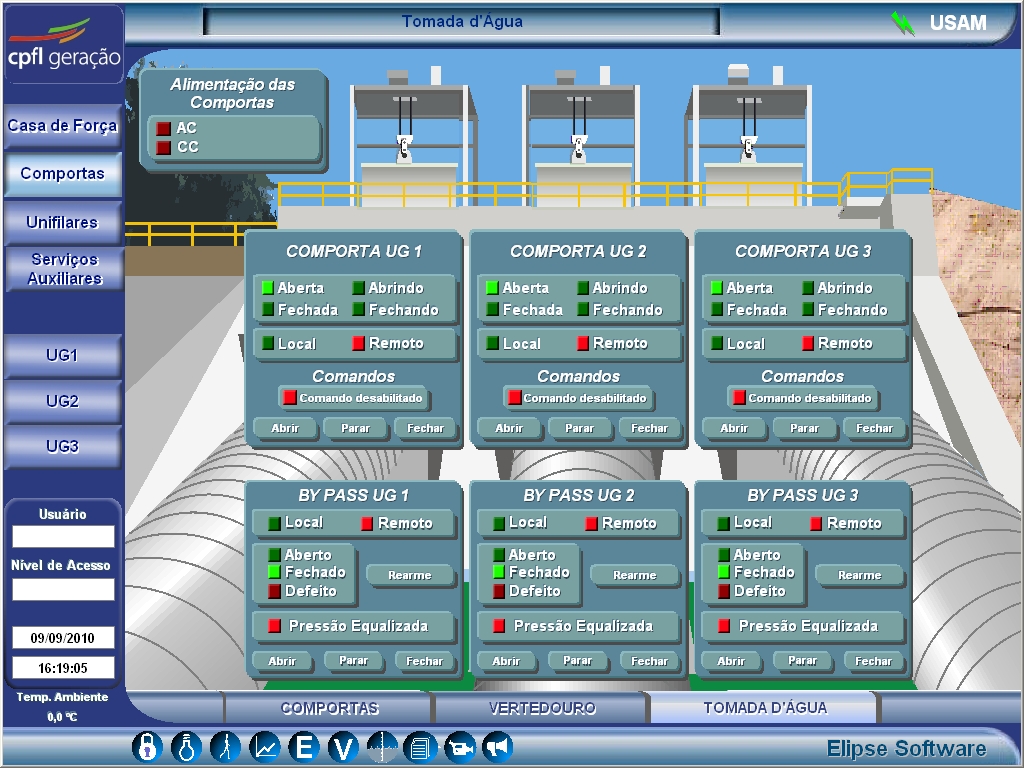
Figure 3. Screen showing the water intake
Before entering the chambers, the water from the river passes through a filtering process carried out with the bars of the sluices. This process is designed to prevent debris in the river from damaging the turbine’s rotor, thus damaging the whole operation. Once in the power chambers, Elipse E3 enables the operator to monitor the water level in order to ensure that it complies with the operating range, in addition to checking whether the floodgates are open or closed.
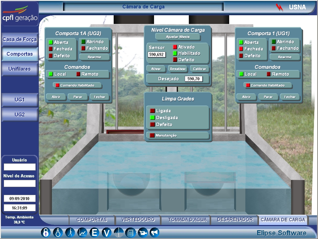
Figure 4. SHPC loading chamber’s control screen
Turbine
From the load chambers, the water flows towards the turbine, a device coupled to an electric generator connected to the network via a power substation. A turbine comprises the following components: spiral case, pre-distributor, distributor, and rotor).
The spiral case is a snail-shaped structure surrounding regions of the pre-distributor, distributor, and rotor. It is connected to the conduit, which connects the loading chamber to the turbine in the input stage, and to the pre-distributor in the output section. Elipse E3 enables the operator to visualize the height of water fall on the spiral casing.
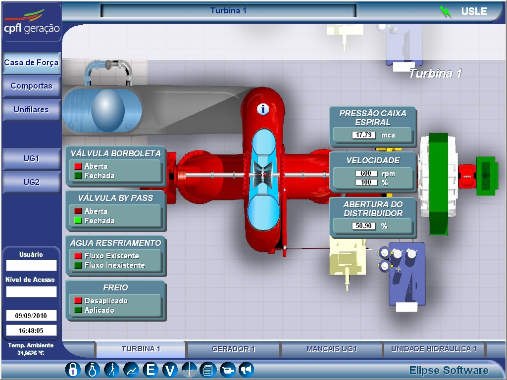
Figure 5. Turbine control screen
The pre-distributor is the responsible for making the water flow to the distributor. It comprises a set of 18 to 24 fixed blades, with a low drag hydrodynamic profile, which controls the current’s flow, avoiding turbulence during runoff. This party does not move, and it is welded to the housing spiral.
The distributor, on its turn, is the device that controls the power of the turbine, once it regulates the flow of water. It also comprises a set of 18 to 24 movable blades that are triggered via a hydraulic mechanism outside of the spiral box. All blades move simultaneously and equally, and this movement is controlled by E3 software.
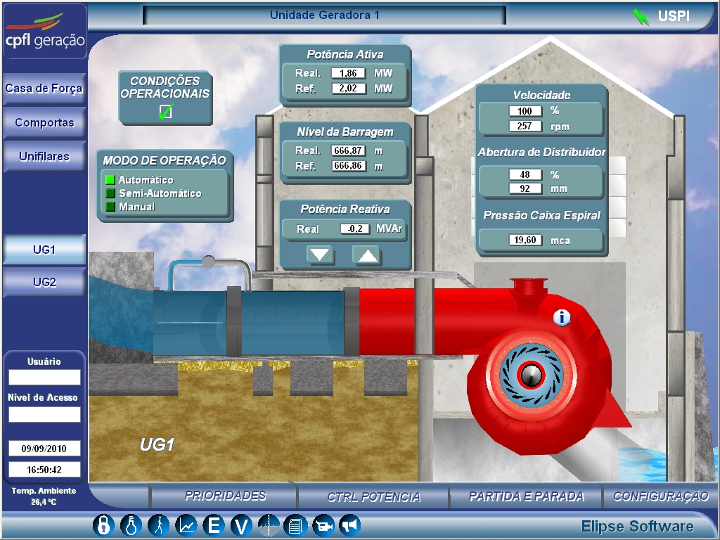
Figure 6. Screen displaying the opening percentage of the distributor’s blades
From the dispenser, the water flows towards the rotor, where hydro energy and gravitational energy is converted into mechanical energy. Once this conversion occurs, water goes into the output duct, whose diameter is usually larger than the initial one, which slows the current flow through the turbine after its passage, returning it to the river. This step of the process, like the others, can also be monitored via E3’s screen, allowing control over the output gates of the SHPC.
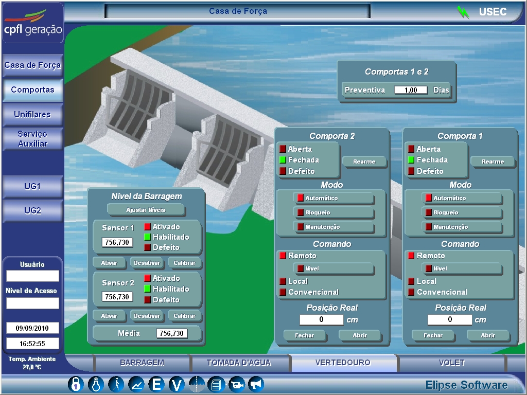
Figure 7. Screen displaying the floodgates through which the water is drained back to the river
Valves, Bearings & Hydraulic Unit
The opening and closing of the butterfly and bypass valves, both located between the load chambers and the turbine, are also controlled by E3 (see Figure 5).The butterfly valve protects and blocks the water flow towards the turbine in case of emergency, thus avoiding possible damage to the structure of the SHCP. The bypass valve is used to adjust the pressure exerted by water in the upstream (region adjacent to the entrance) and downstream (after the exit) of the butterfly before it is opened.
Between the axes uniting the turbine rotor to the generator there are bearings, which are devices whose purpose is to sustain and even the connection between both structures on a stable and sturdy way. However, to make sure this happens, the bearings should be lubricated and cooled constantly, which minimizes friction and heat on them along the axes.
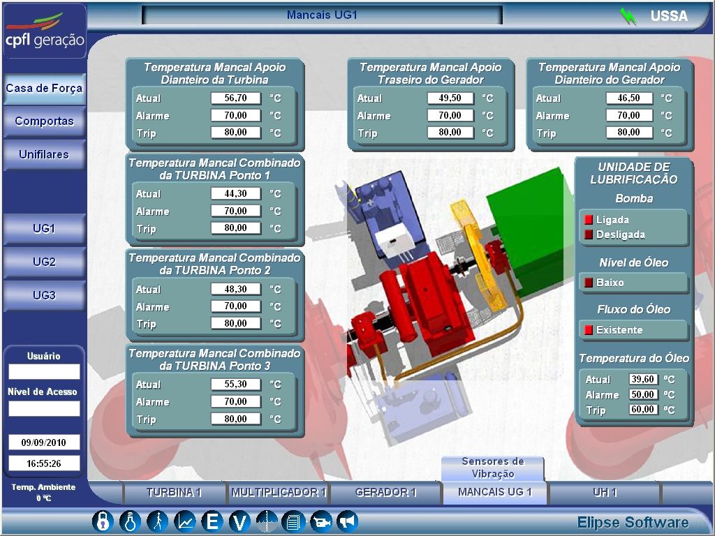
Figure 8. Screen displaying the pop-up control of the bearings
Both processes (cooling and lubrication of the bearings) are held at “Hydraulic Unit”, monitored by Elipse E3. Through a single screen, the user can control the pressure, temperature and lubricant oil filter, as well as the pumps responsible for pumping oil to the bearings constantly.
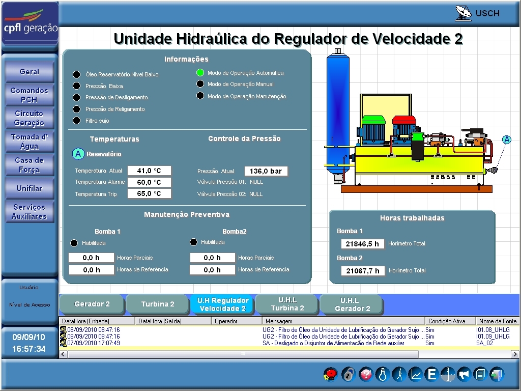
Figure 9. Hydraulic Unit Control Screen
Generating Unit
Finally, the software allows supervising the generating units of the SHPCs. Through a single screen, you can view the current values of active and reactive power, voltage, electric current, and frequency.
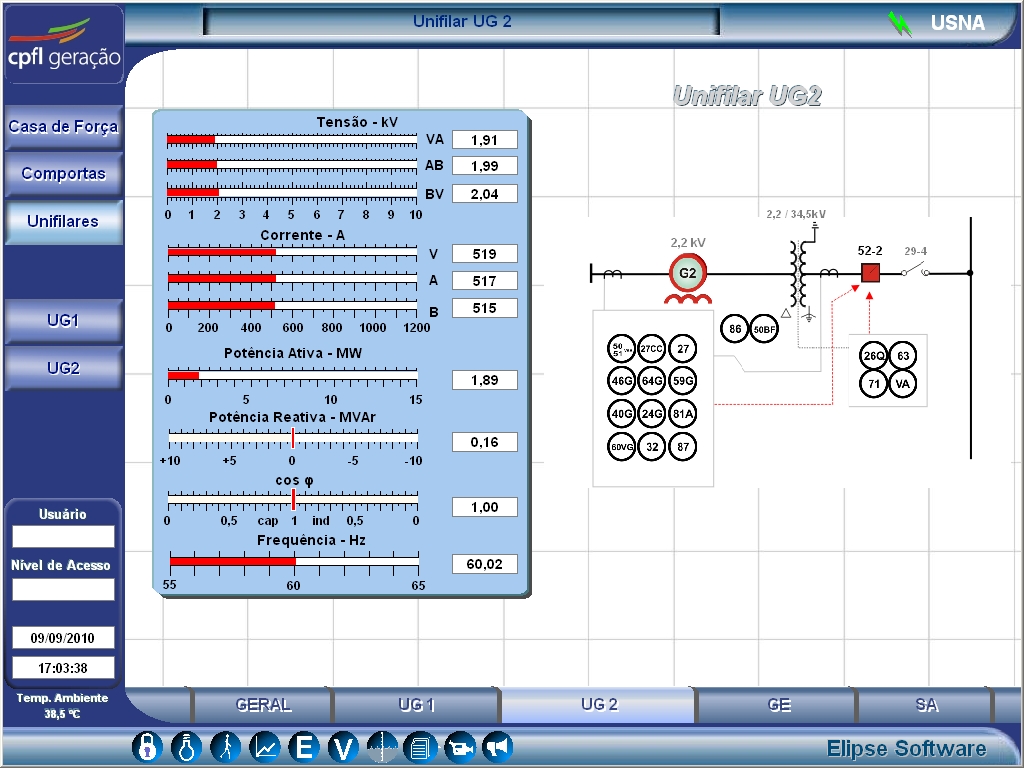
Figure 10. Generating Unit Control Screen
Unifilar
In addition to the control of the generating unit, Elipse E3 also has a screen that displays the whole unifilar diagram. The unifilar is nothing more than the simplified representation of an electrical system, whose goal is to reveal the interconnections between the devices involved in power generation (breakers, disconnectors, transformers, etc.).
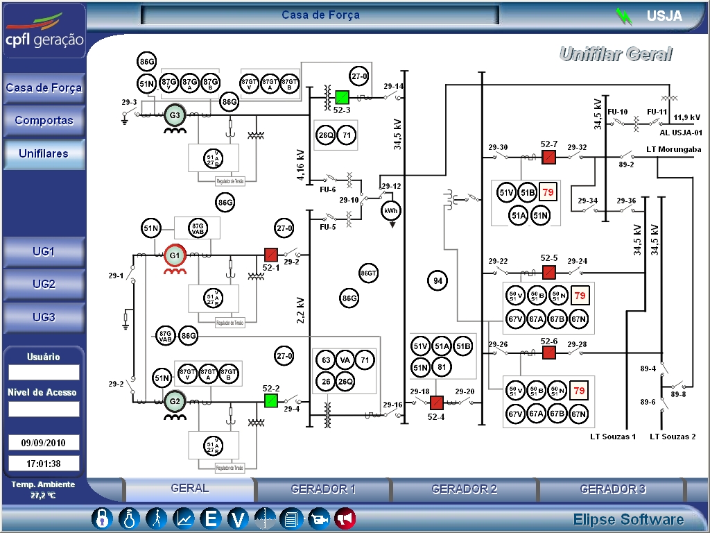
Figure 11. Screen displaying the energy unifilar
Benefits
- Optimizes the control of CPFL Group´s 17 SHPC.
- Remote control of the SHPCs and of the process of generating energy, via E3 screens, without leaving the GOC.
- Monitoring of water intake from the river’s upstream to the SHPC’s crossing of the entry gates.
- Control of the level of water inside the load chambers.
- Control butterfly valves and bypass allowing the passage of water in a balanced way, chambers of load to the turbines.
- Control of the status of different parts comprising the physical structure of the turbines (spiral case, pre-distributor, distributor, and rotor).
- Control of bearings to avoid damage due to excessive friction or heating.
- Control of bearings’ temperature, pressure and lube oil filter.
- Control of the different measurements (voltage, current, power, and frequency) and components comprising the power generating units.
- Display of unifilar energy.
- Control of all protections of the machinery and substation of the plant.
Datasheet
Client: CPFL Energia
Systems Integrator: CPFL Energia
Software: Elipse E3
Number of copies: 16
Platform: Windows XP and Windows Server 2008
Number of I/O points: 15000
I/O Drivers: Modbus, Moeller, GEETH, ABNT NBR14522
